Mapping Guidelines
Image acquisition
Image acquisition is curcial for obtaining good mapping results. The following points are most critical:
- 80% forward overlap and 70% side overlap are recommended
- A NADIR camera gimbal is not required but recommended
- WP_YAW_BEHABIOUR should be set to 0 (never change yaw) and the copter should takeoff nose forward in the main direction of the flight path
- Flights should be conducted between 10am and 2pm for optimal light conditions
- Do not fly if it is too windy
- Do not fly if the K-Index is > 4 (see graph on the right for current data)
- Non-NADIR Images should be removed manually – especially from turns
- Only images between the first and the last waypoint should be processed
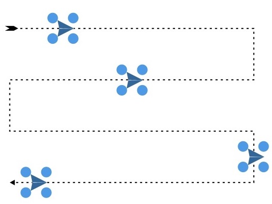
- Flight paths should be parallel
- Do not combine images of different missions and especially different flight altitudes
- Do not combine two missions of non-adjacent areas
- When mapping forrested areas the image over- and sidelap should be increased to about 90% and 80% and the flight altitide should be higher.
Image format and handling
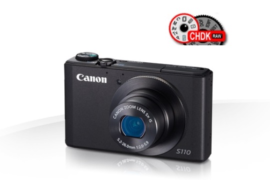
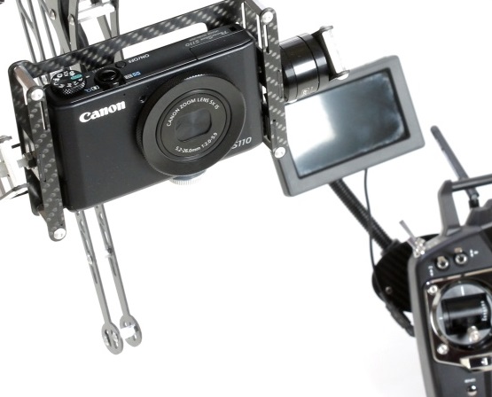
We recommend to use CHDK enabled Canon cameras together with our KAPTURE script for precise georeferencing. Regarding image processing the following is of importance:
- Images should not be pre-processed (EXIF tags, …)
- Images have to be in JPEG (8 bit) or TIF (8 bit) format
- All images must be taken with the same camera and the same focal length
- Images should not be renamed or renumbered
- Image numbering should be reset for each mission (use an empty SD card, and change the camera settings accordingly)
- For georeferencing it is important to know how many images were taken before arming but were triggered via the autopilot - for example using the Ch7 switch
Ardupilot log file handling
- Plain text 3DR Solo, AC 3.3 or AC 3.4 .log files are required for precise georeferencing
- EKF, GPS and Camera trigger data must be enabled/logged
- A new log file is required for every mission
- Logging should not start before arming
- All images, the UAV .log file as well as the CHDK camera .cam file (if available) should be placed in one directory before selecting a workspace in Mavis
- Images taken with UAVs using other autopilots images must be geotagged
Further notes on mission planning and UAV surveys
Overlap
- For UAV photogrammetry large forward and side overlaps are required.
- Under windy conditions and if the camera is not mounted on a (NADIR) stabilized gimbal a forward overlap of 85% and a sidelap of 75% is recommended. This helps to compensate aircraft instability due to wind gusts.
- Using a stabilized gimbal the forward overlap can be reduced to 70-80% and the side overlap to 65-75%.
Camera mount
- Under windy conditions and typical mission speeds of 3-10m/s, pitch and roll angles of > 10° may occur. These lead to distorted image footprints and thus require a higher overlap.
- For ortho-rectification a maximum angle of 3° is recommended. This can be assured by using NADIR stabilized gimbals. This helps reducing the effect of different viewing angles and thus illumination differences between neighboring flight paths.
- A stabilized NADIR mount also allows for fast direct stitching.
Yaw behavior
- For security reasons (i.e. knowing the orientation of the UAV at any time even at the end of line of sight or after a short distraction), easier interpretation of the raw images and to reduce illumination artifacts (to some degree), copters should be operated with a fixed yaw (not facing the next waypoint).
- Yaw should be set to the hatch angle, i.e. parallel to the main flight path. For APM:Copter this is WP_YAW_BEHABIOUR = 0.
- Suggestion: position the copter nose forward in the main direction of the flight path (called hatch angle in Tower) before arming.
- If required, yaw can be adjusted in Auto mode. A derivation of +-10° is not problematic. *
Shadows
Shadow boundaries are often taken as key/tie-points. However, as sun angle is constantly changing the shadows are moving – resulting in inconsistent the key point locations. This will cause artifacts in digital surface models at the shadow boundaries.
Key point detection is also problematic in shadows because of low contrast.
To reduce the influence shadows imagery should be collected from 10am to 2pm with a preferred sun angle of 40-60 degrees.
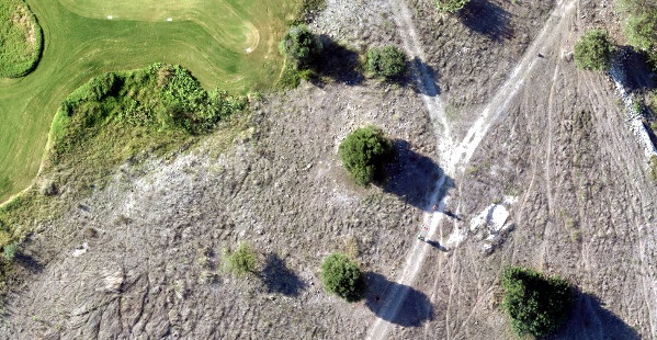
General considerations
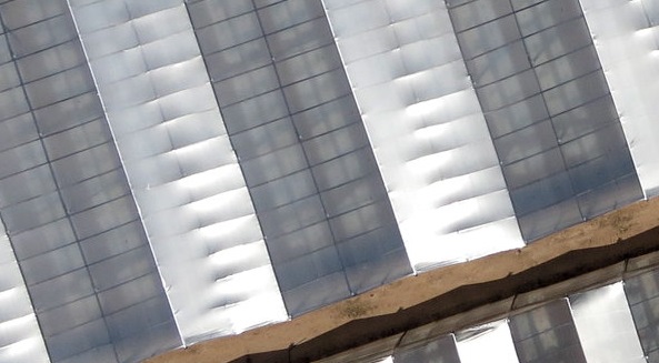
Reflecting objects such as cars and water bodies can lead to inconsistencies in tie-point detection. This can result in uncertainties when deriving digital surface models in these areas.
Tie-point detection on vegetation can be problematic under windy conditions. In this case the location of the keypoints will be inconsistent.
Deriving digital surface models is problematic for trees without leaves because neighboring key points can either be from the soil surface or from a branch of the tree.
The lower the image overlap the higher the uncertainty.